|
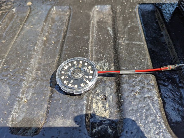
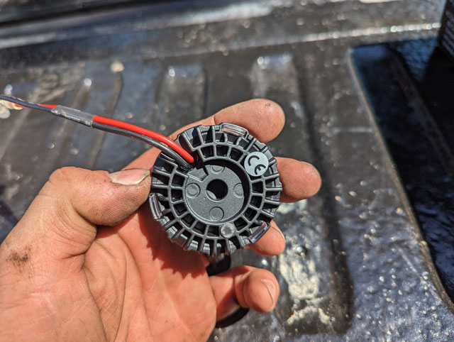
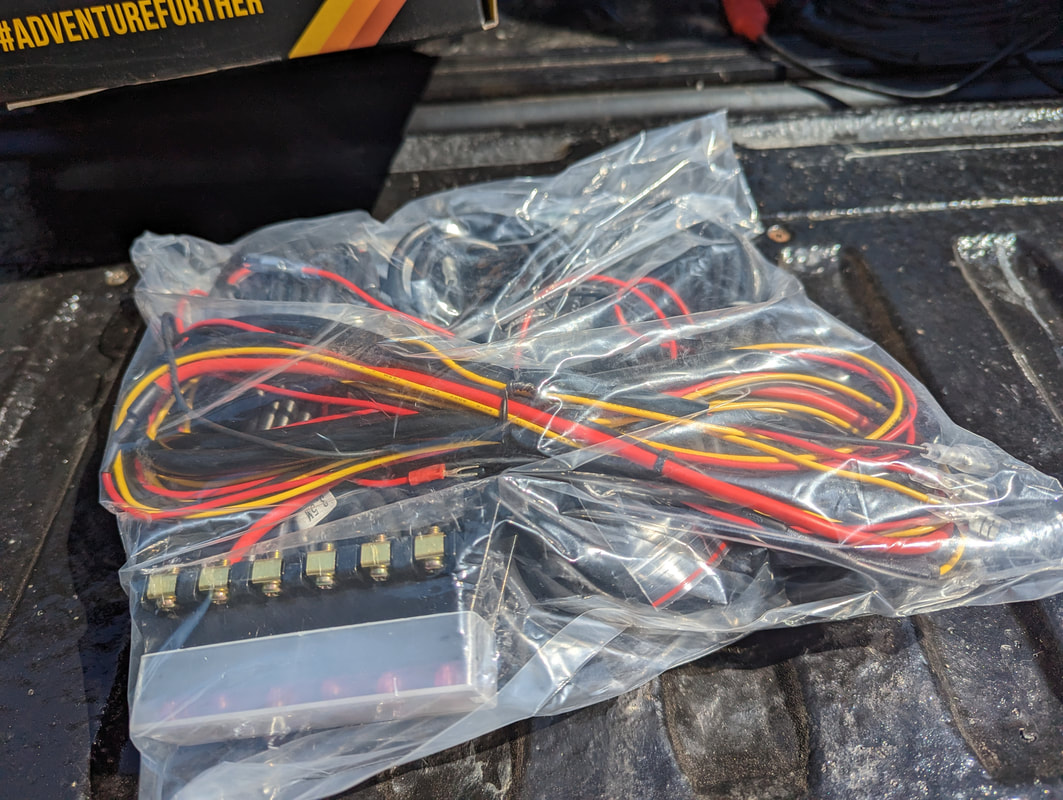
So i put together a video going over, in detail, how we installed and wired the Autometer oil pressure and transmission temperature gauges in our '90 one-ton Bronco Project: Ive been running around trying to get the '90 done, and havent posted any updates. So here's where we're at: I couldnt get the brakes to bleed, ended up having to replace the RABS module because it was seized 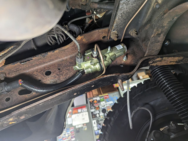 I had a code for EVP below minimum voltage 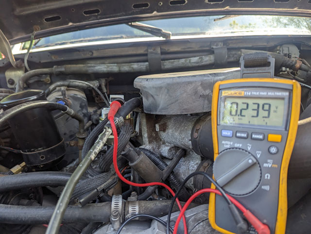 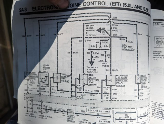 Which turned out to be a defective EGR- the nipple for the EVP to seat against wasnt in the EGR 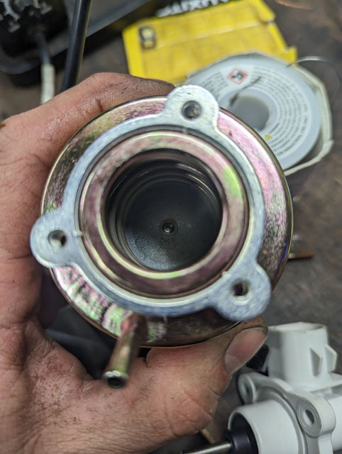 New one installed, problem solved! 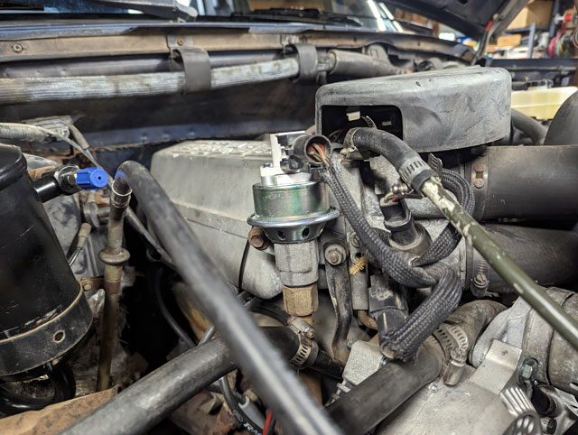 I redid the battery cables, so i could add an anderson plug for the remote-mount winch: 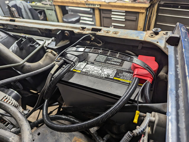 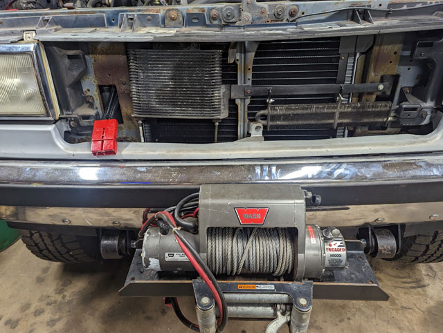 and then i finished off the interior, by adding a pair of Autometer gauges; oil pressure and trans temp 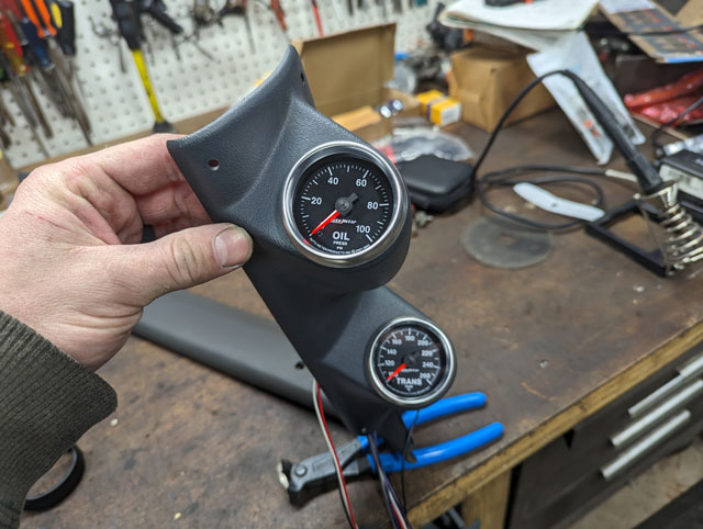 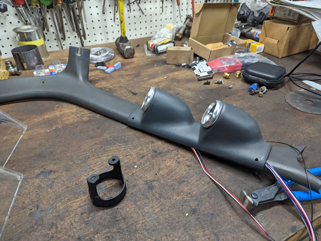 Built a standalone harness for the gauges that has one plug for power/illumination, and a second plug that goes to both sensors 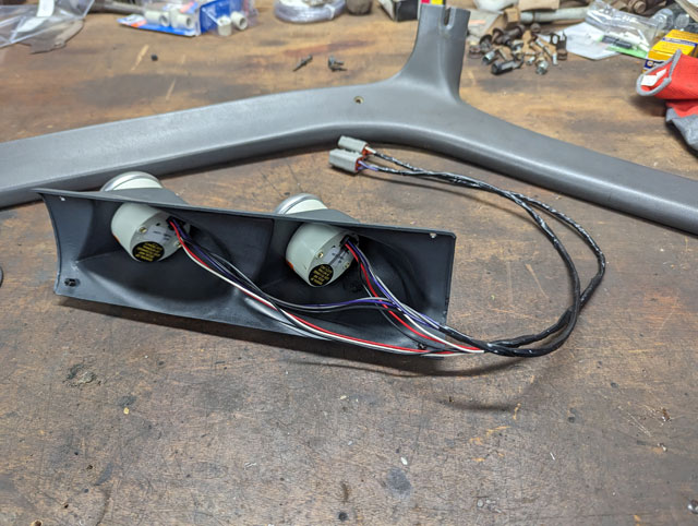 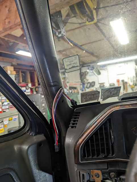 Back when i was putting the accessory drive together i installed the Autometer oil pressure sensor on a Tee with the OEM sensor in the factory port 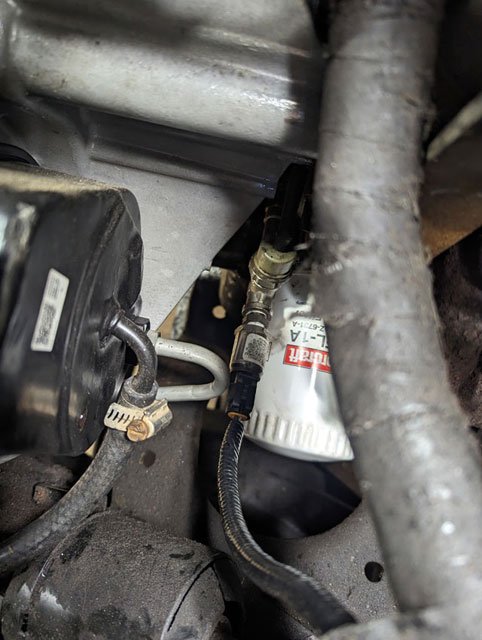 I thought i had a pic of the trans temp sensor, but apparently not. Its in the test port for the E4OD. Pic of it installed on the 96: 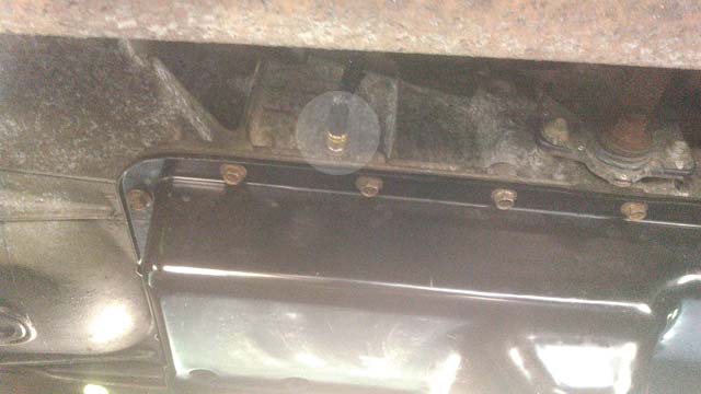 While i was in the interior, i pulled the cluster out so we could go full led: 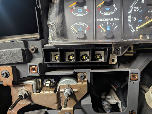 ..and done! 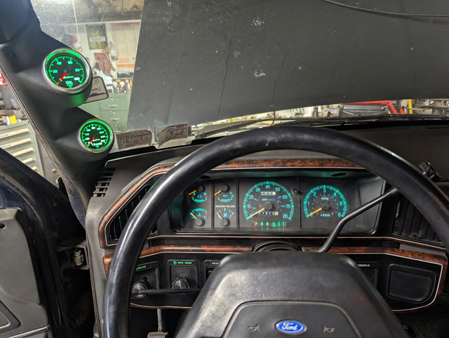 This was the scene earlier in the week  ...when i started to wire up these! 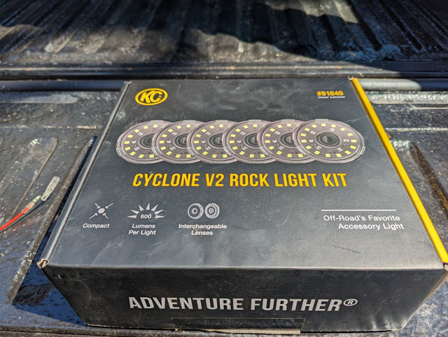 KC's Cyclone V2 rock lights! I have wanted to put a set of rock lights in for years and never got around to it. Im glad i waited as long as i did though, because this kit is awesome. It comes packed with 6 lights: 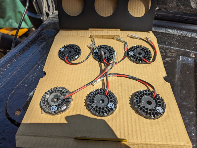 Up close, theyre nice pieces:
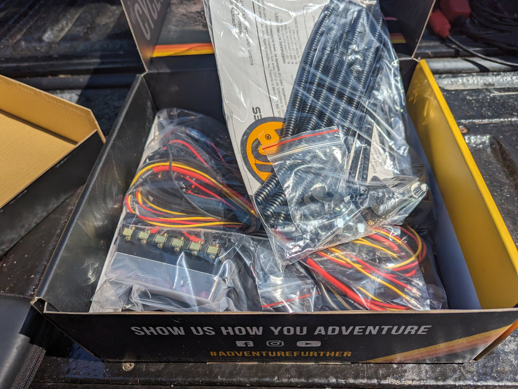
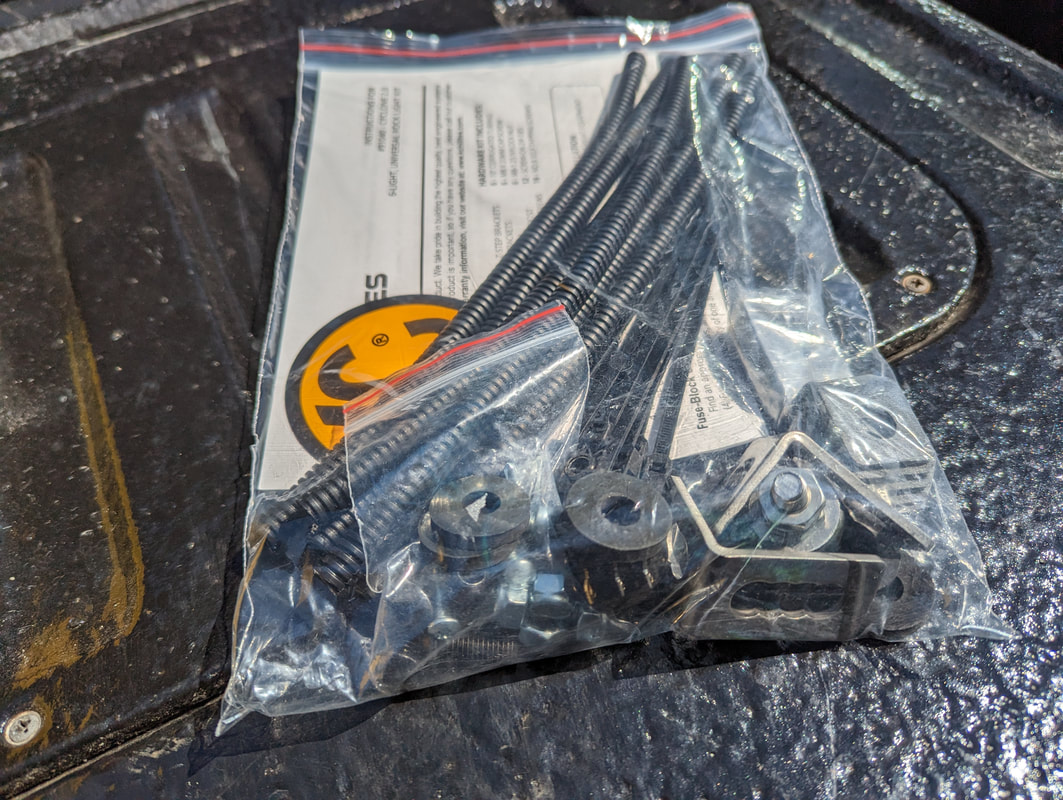
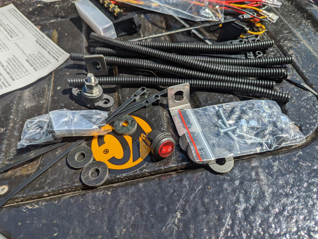
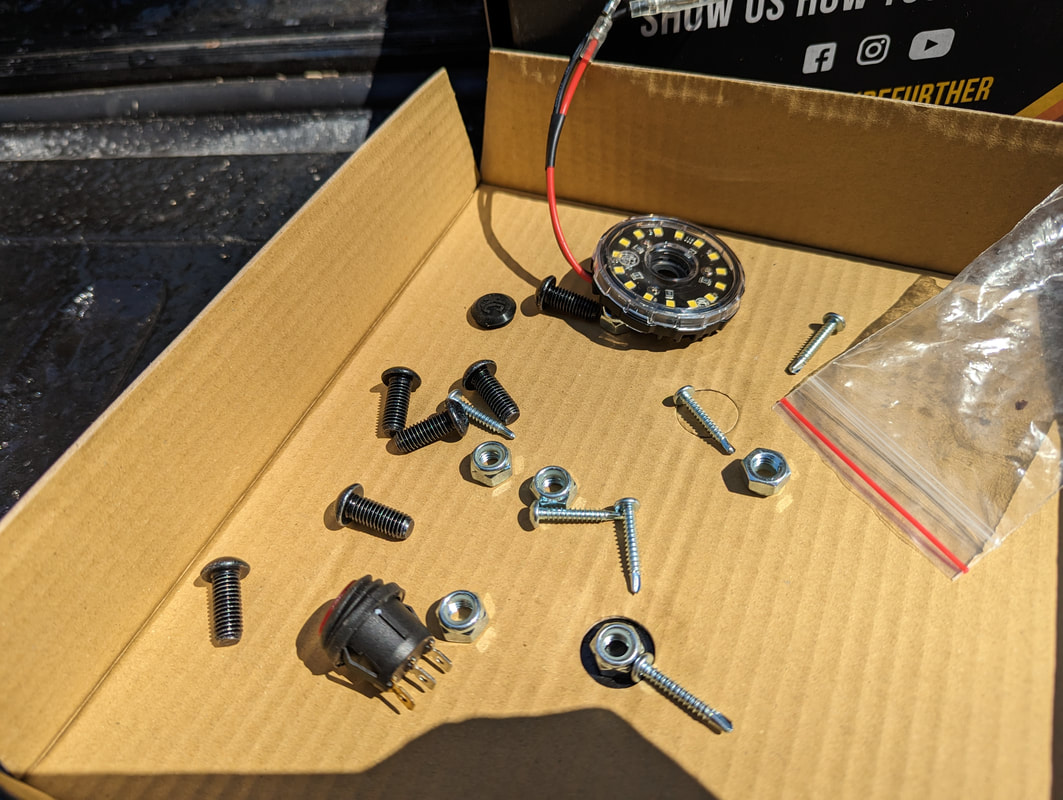
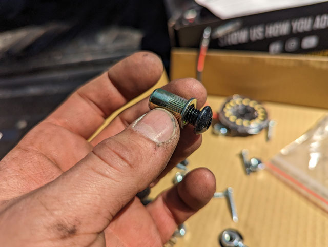
It comes with a pretty nice install kit too: Amongst some of the hardware are these M8 button heads to hold the lights in place. I elected to use rivnuts instead of the lock nuts, to make the install easier:
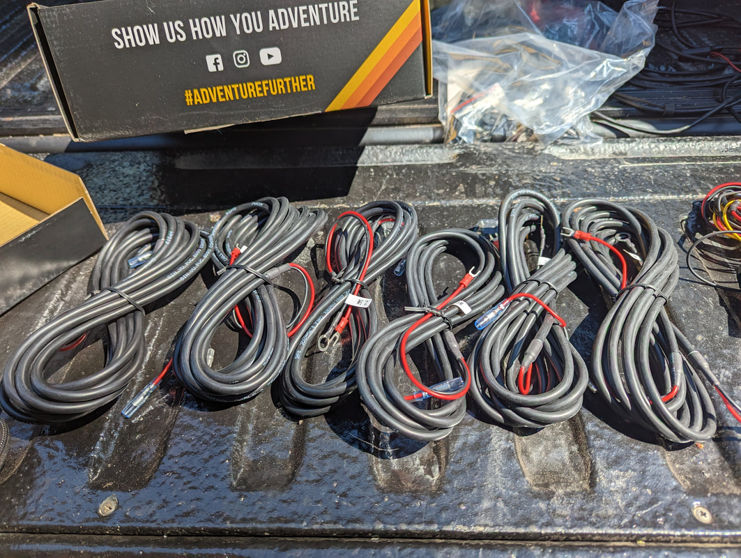
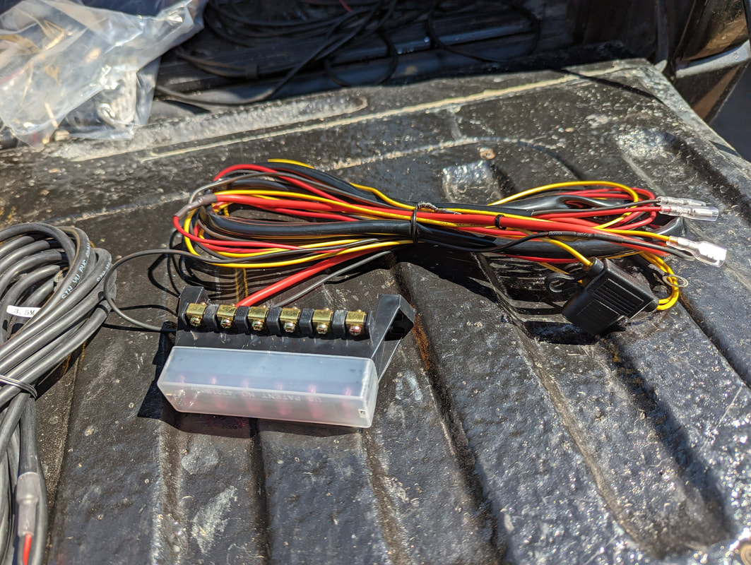
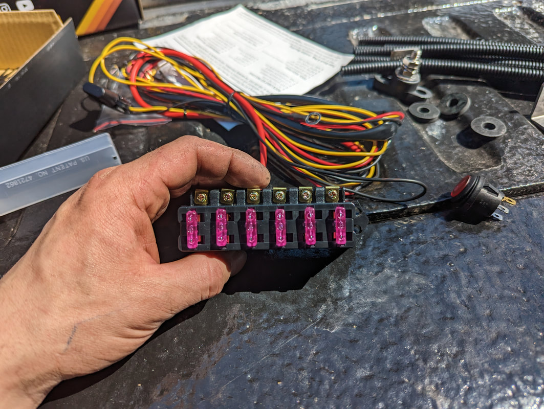
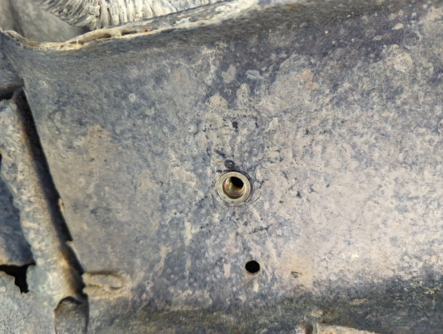
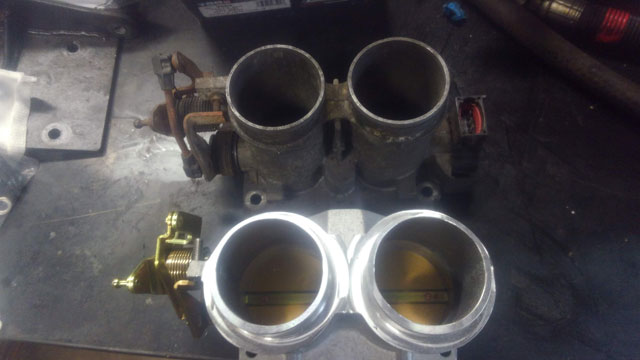
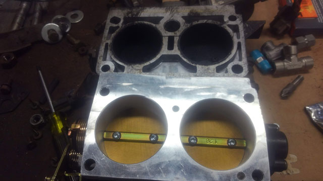
Up front, im just outside the core support body mount: 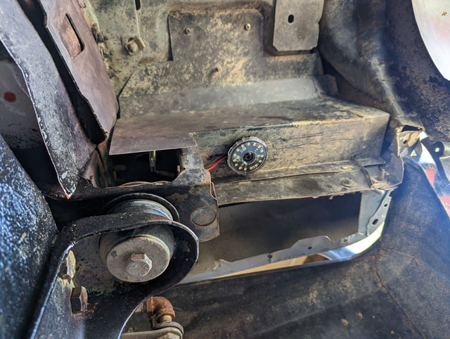 In the middle, Im on this body support just outside the frame. Im not thrilled with the way its mounted, but it puts the light where i need it 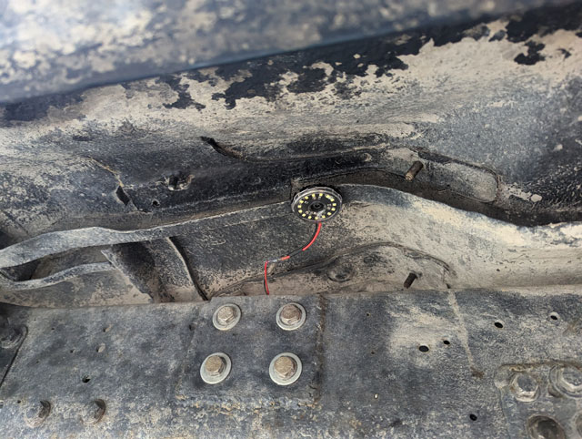 And then for the rear, im in the rearmost body structure, just behind and outboard of the shackle hangar: 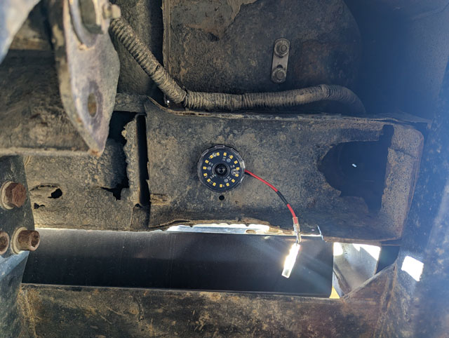 As for the wiring, i only used part of their kit. The wiring itself is nice, but a bit short for a fullsize rig. Would work fine for a short wheelbase rig like a jeep or zuk. Anyways, i was able to use their harnesses for 5 of the 6 lights, and then i ran my own wires for the 6th since it was too far away. I did use their fuse holder though. I kind of liked the idea of having a separate fuse for each of them just in case i damage one, and it simplified the wiring under the hood: 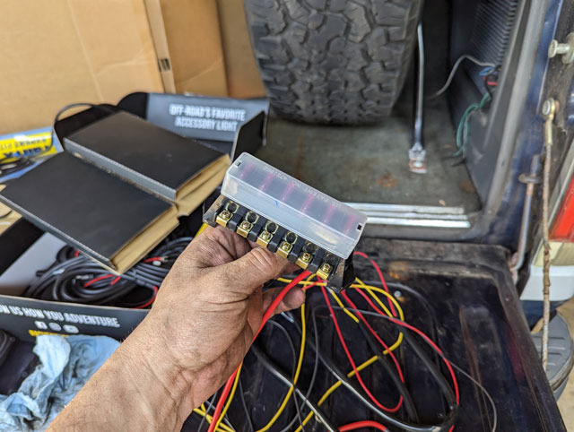 They want you to power this directly from a switch in the dash, but i had a spare relay in the aux fuse box i added under the hood, so i used that to power everything 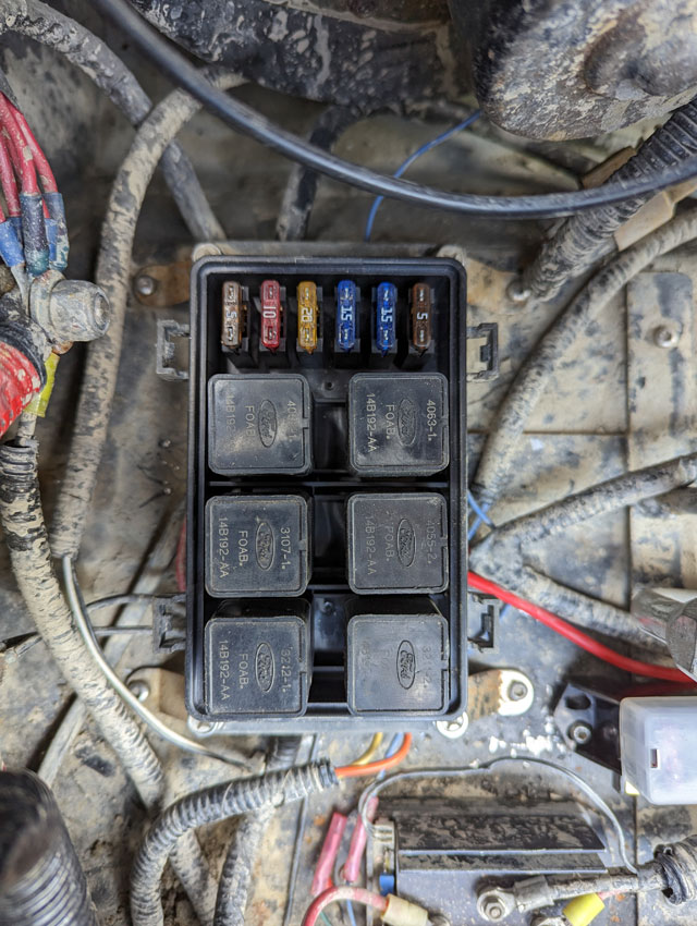 Conveniently, i also already had a spare set of wires run to the dash to trigger said relay, so it was just a matter of adding another switch to the dash, and connecting the existing wires 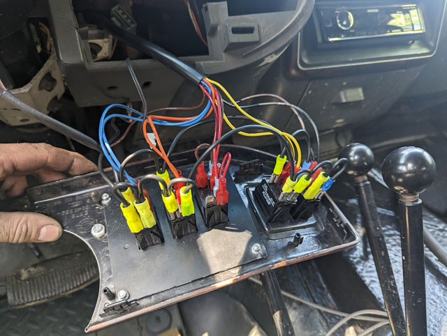 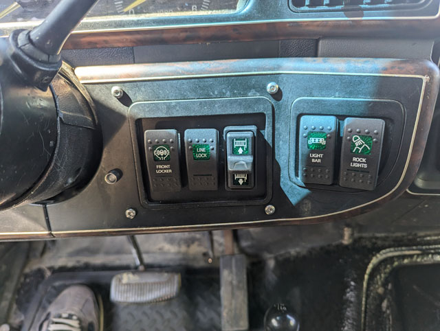 That stuff is boring though, lets see how they look! 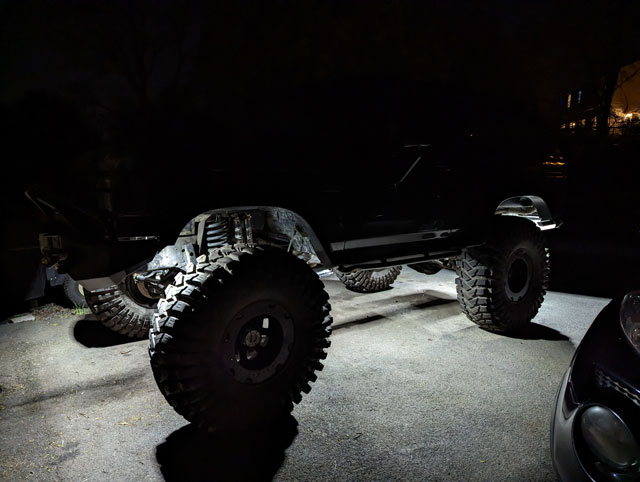 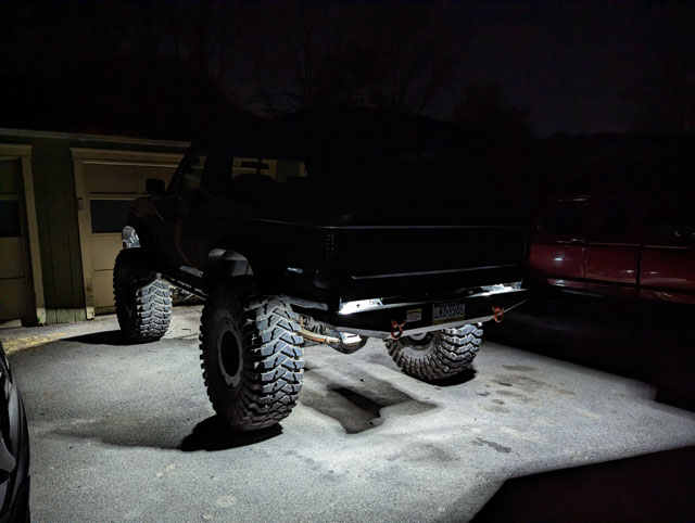 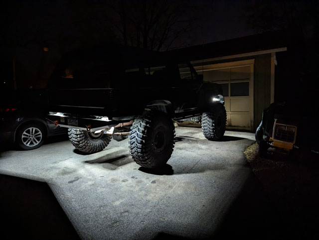 Im diggin it! Its kinda funny how the taper of the rear bumper causes it to cast that hourglass shape out back, but theres nothing i can do about that. I think this is gonna work out great, i guess we'll find out next time we're on the trail after dark! Let's fix that tailgate! 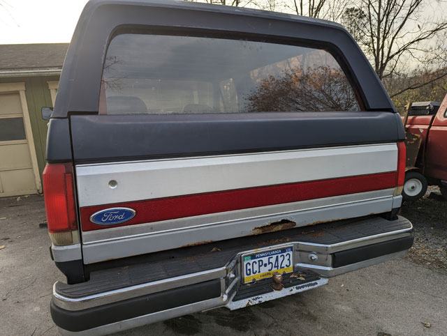 Couldnt get the window to go down. Had to resort to drastic measures to get the regulator out, but we were successful. We had some issues with the wiring harness that needed to be resolved 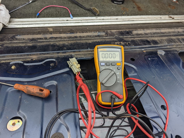 ...but in the end we were successful! Man, the weather has not been cooperating! After about two weeks of rain, i spent a couple days mowing the jungle that was our yard. So now im finally caught back up, and progress can resume! First up, theres now a tee in the OEM port, so i can run both the OEM & the NVU oil pressure senders: 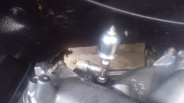 New Ford Performance 47# injectors: 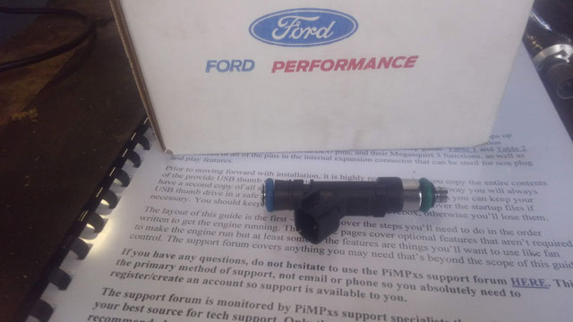 ...and BAM! Injectors, fuel rail, wiring harness, and plenum installed! 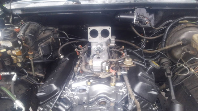 New BBK twin 61mm throttle body: 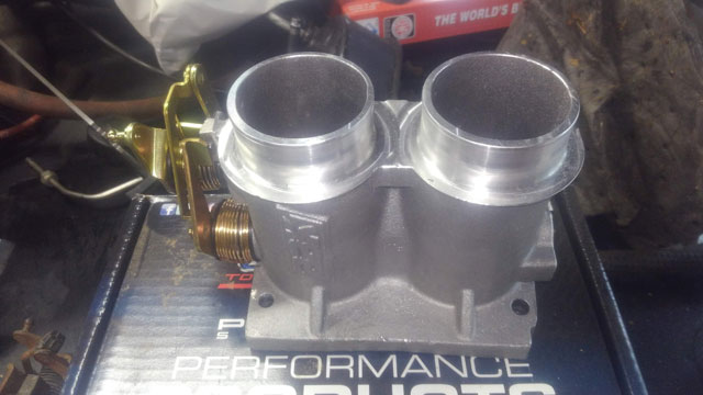 This thing is a beast; way bigger than the OEM throttle body. Should flow a ton more air:
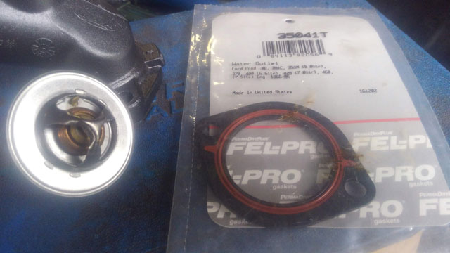
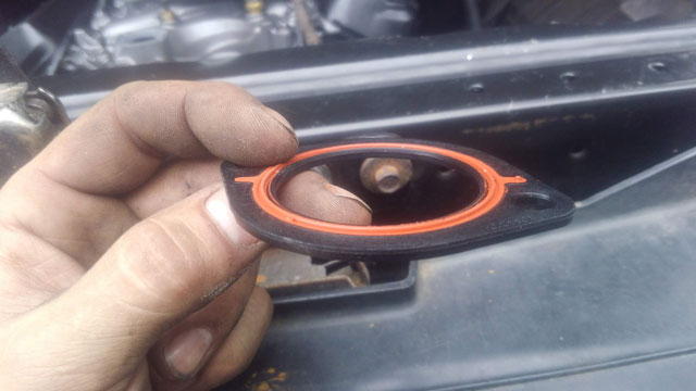
Also picked up this cool Felpro thermostat gasket, p/n 35041T. Supposed to solve the typical ford leaky t-stat housing issue. Its ~1/8" thick, and has an o-ring seal on both sides. Its a pretty nice piece, and looks like it should work well
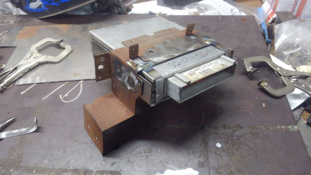
Progress! Now its starting to look like something! 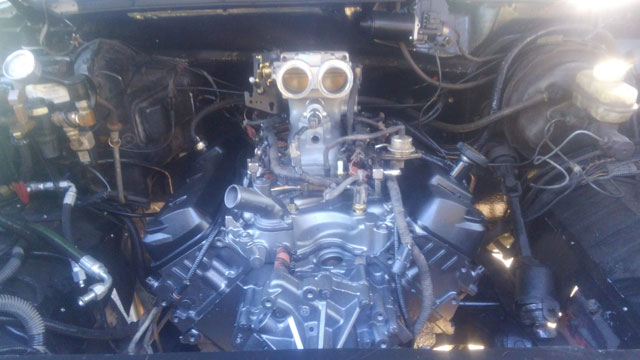 Distributor all ready to go with new o-ring, cap, rotor & TFI module: 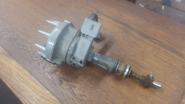 Engine at TDC & distributor installed. Plus a big win- the oil cooler is installed! 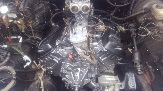 My frame notch was a huge success; Theres lot of room for the oil cooler, and it fit up in there easily with plenty of room to spare. 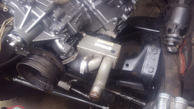 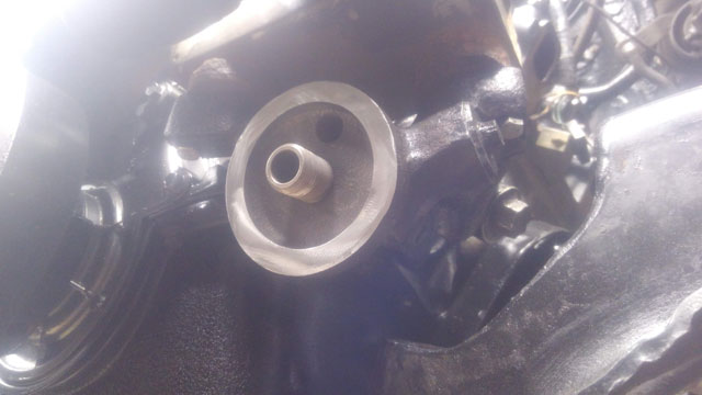 Super excited about this one, it clears like it was made that way by Ford! From here on out, i think everything left to do is basic reassembly, so progress should speed up. My torque converter showed up yesterday too, which was the last item i need to finish reassembly. If all goes well, i might be able to fire the engine in about a week's time! Despite the absurd weather, i have still succeeded in making some headway on the motor install. First up, i am trying to finalize the Stinger PimpX install. As mentioned a little while ago, this thing is a 100% new ECU, based on the Megasquirt 3 technology. It is designed to work with the OEM harness & sensors, however, if you look closely, it has its own on-board MAP & BARO sensors.  It comes with a flash drive that includes a custom tune, and all sorts of tuning and programming software, as well as some PDFs detailing the whole install and tuning process. One thing i did, was to get the install manual PDF printed and bound by Staples. Its pretty cheap, and its nice having it as a reference since its ~35 pages long, and you need to reference it for initial setup & tuning. 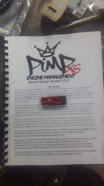 I know its difficult to tell in the photo, but this page is going over our setup. You need to configure the ECU for your motor size & injection type. Sounds complicated, but theyve actually made it quite simple: 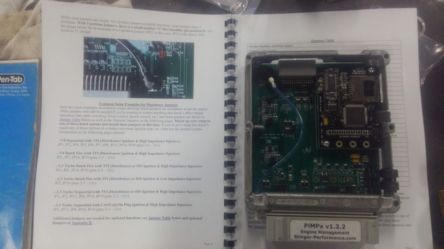 The ECU comes with a handful of jumpers you install on the board to set up if youre a V6, V8, batch or sequential EFI, Mass-Air or Speed Density. In my case, all i need is to install these 4 jumpers, and im good to go! 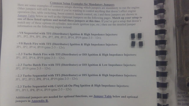 There is a TON of other things you can customize. Built in boost controllers, electric fan controller, you can configure your ignition type (including TFI, DIS, EDIS CDI box, etc), boost controller, nitrous controller, you can add cam & crank sensors, more O2 sensors, VSS (if not already equipped), there is a ton of customizing you can do. There is an extra port on the bottom of the ECU for adding in all the additional items the stock 87-95 ECU did not support. 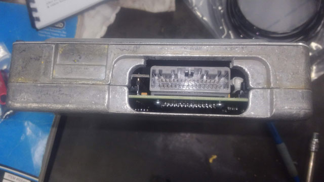 included is some high quality silicone(?) tubing for the map sensor, and a USB cable for tuning 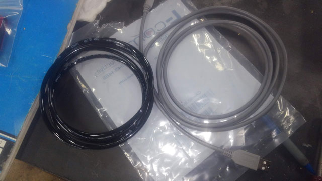 There is a USB port on the side, along with a SD slot for data logging. You need access to the port to load the tune (this will come later on in the install), and thanks to my relocated ECU i did not. 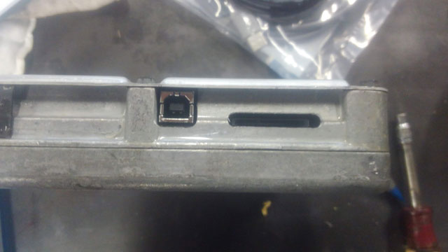 Back when i was getting ready to install the dash, i built this bracket to relocate the ECU:
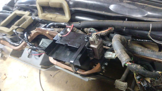
It was a clever design, but it has to be modified. Thankfully i made it bolt-in! So i carefully removed it and notched this side, to give me access to the USB port 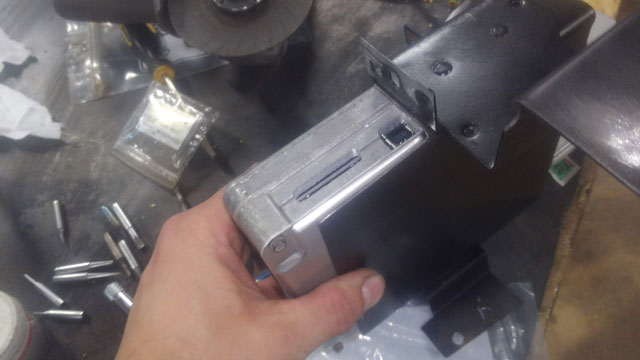 So with that done i need to move on to some wiring mods. First things first, we need to add a wideband O2. The ECU will work with either the stock narrowband sensor or the wideband. If you use the wideband you gain a self-learning feature, which i definitely want. The install is simple, simply supply the +5 reference from the wideband controller directly to the signal wire that the original narrowband sensor goes to, and eliminate the stock O2 sensor. It seems simple enough, but i decided to do what i usually do, and make it more complicated! So, this pic shows where i mounted my wideband controller; up high in some free space above the brake/ebrake pedals: 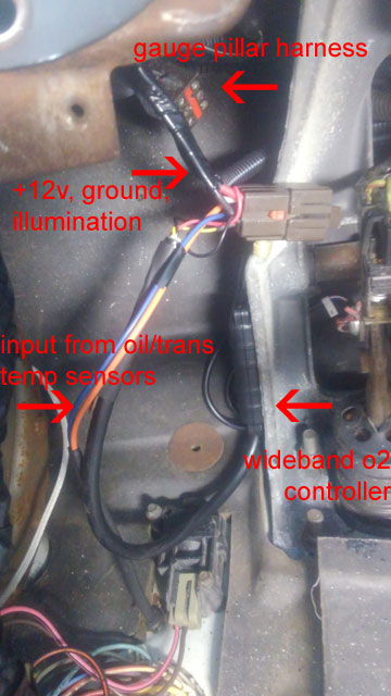 This means the +5v signal wire is right near where the factory ECU would be. So rather than cut into the stock harness, i decided to add a wire to the ECU extension cord i made. So lets take that back out! 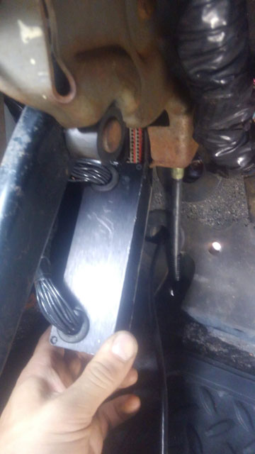 Once opened back up, you can see the board offers not one but two seperate places to tie into each circuit, specifically for piggybacking for aftermarket ECUs and controllers. So all i did, was add a signal wire directly to the signal circuit for the stock O2 sensor, Pin 29: 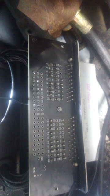 All closed up and reinstalled, with the new signal wire hanging out and ready to be sleeved/run to the controller. 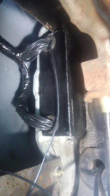 Once that was done i reinstalled the kick panel and tied that wire into my O2 signal. So now ive got both signals wired in, w/oo having to cut or modify the stock harness which is a big win in my book. So now lets move under the hood. This is the wiring for the OEM MAP sensor + O2 sensor. Its a lot of wire, and we dont need it anymore. 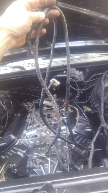 I dont like the idea of simply cutting the wires off, so instead i cut them back, crimped new pins on the wires, and installed a 8-pin plug off a junk harness i had laying around 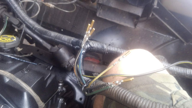 That looks considerably better! Almost like Ford made it that way. 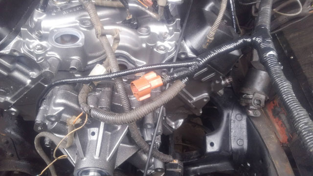 So here's what we removed. Not discarded though; ive made it us as a companion harness that will plug back in and then put away in a box on the shelf. This way, if i ever want to add the stock sensors back in, i can, without having to do any additional modifications to the harness. 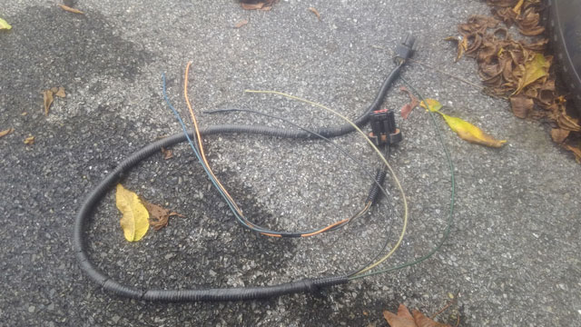 So this should complete the wiring mods for the PimpX, which means its time to finish the motor install! Progress has been made! First up, i got my air-fuel ratio gauge installed. I removed my a-pillar trim, removed the gauges, and removed my standalone harness for the gauges
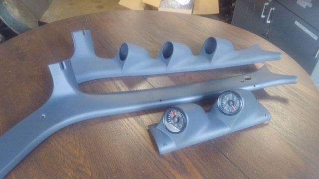
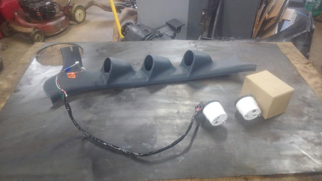
Wiring harness dissected, and A/F gauge wiring added! Since its a gauge from NVU the wiring is basically the same. So i spliced in the power, ground & illumination wires, and only had to add a single wire to the harness- the +5v reference from the wideband controller. So overall a pretty easy job to do. 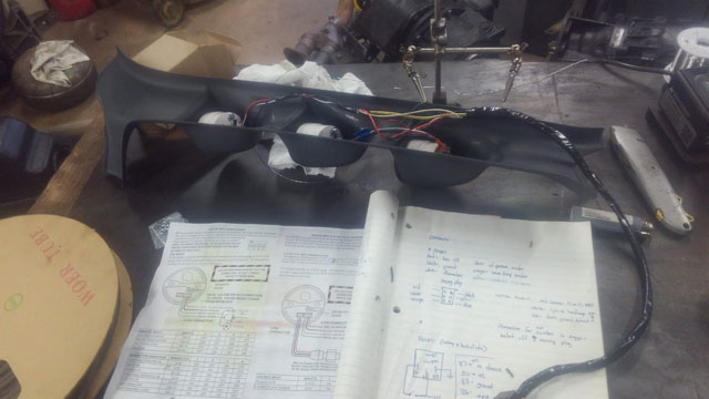 Bam! installed. 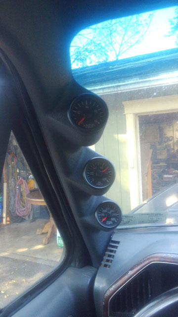 The Glowshift pod fits pretty good actually, but i did trim the top slightly where the windshield trim fits up against it, so it would fit a little tighter. Just some minor work with a razor knife, nothing major. I also took the time to lay out where the original trim screws go, so i could use the OEM screws to go thru both the pod & the pillar so no extra hardware to remove, and it actually looks pretty clean. So, that's done, moving on. I got my new ECU from Stinger Performance, the PimpX! 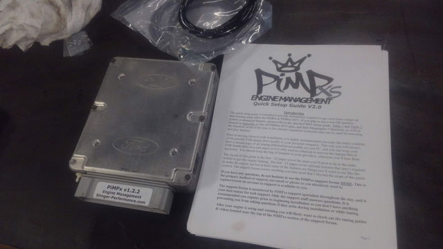 It comes with a bunch of stuff, including a pretty in-depth 30-something page PDF, which i printed off for a reference since the wifi in my garage sucks. They actually want you to open it up, so here we go! 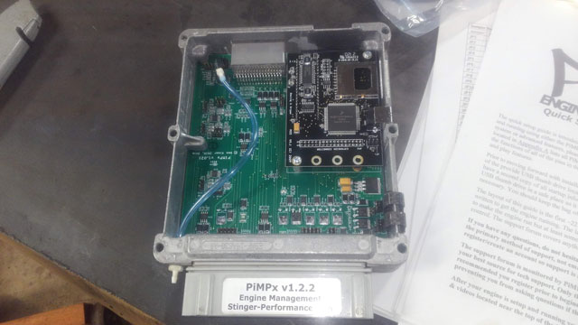 If youve ever been inside your ECM/PCM, then you know it looks nothing like this! This is a 100% custom-built ECU based off the Megasquirt III. It has a bunch of jumpers you need to install in the board to configure your unique setup. They intentionally dont install any just so you have to go thru it and do it yourself, which i actually kinda like since it forces you to set it up exactly for your vehicle. In my case, its only a couple jumpers since im still batch-fire, Speed Density, and running the stock TFI & ignition compnents. It supports a ton of stuff like sequential EFI, coil-on plug, boost switches for forced induction, narrow or wideband O2 sensor(s), it has its own electric fan controller....the list goes on. Im still reading thru the PDF, but im pretty sure i know how im going to configure mine. It uses its own built-in MAP sensor so i have to delete the OEM one, and run the supplied vacuum line from the intake right to the ECU. Also, i am going to be using a wideband O2 in place of the factory narrowband (which gains me self-learning programming), which means i only needed 1 o2 bung in the exhaust, and i will have to tie the wideband controller's output into the oem signal wire from the original narrowband sensor. I think this is the only modification i need to make to the wiring harness tho, everything else should just work like stock. I still have more reading to do on this, so there will be more updates on this over the next couple weeks. Heres the big one though: 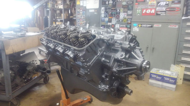 The motor is done! All ive got to do is install the motor mounts & flexplate, and sometime next week she's going back in the bronco! parts 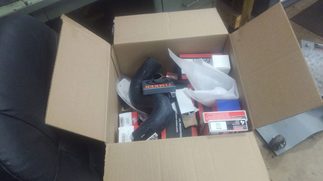 lots and lots of parts 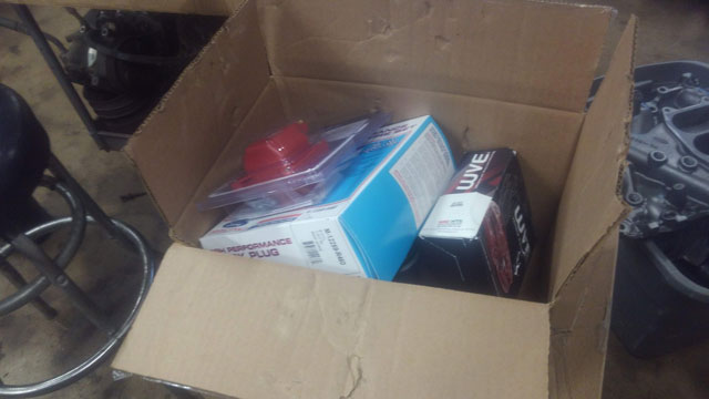 This is basically every sensor for the motor plus tune up parts, gaskets, etc. It also includes a wideband O2 + controller! 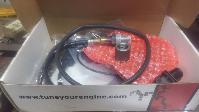 This is Innovate Automotive's LC-2 wideband O2 controller. Fully tunable controller, but does not come with a gauge, which is fine since im getting one to match the other gauges i already have from NVU. I mocked up the exhaust in the bronco, and found a good place to install a bung for the wideband sensor, just behind the stock sensor: 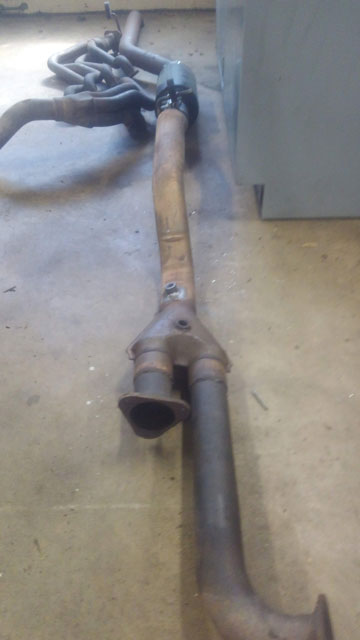 I removed my 2-gauge pod from my pillar, and am installing a 3-gauge pod from GlowShift. Its actually a pretty nice piece and fits very well.  This is the harness i built for the oil pressure & trans temp gauges; its built around a 6 pin connector, and i was only using 5. This works out super conveniently, because i only need to add 1 wire to this harness for the air-fuel ratio gauge- the signal wire from the wideband controller. The rest of the wires for the gauge are all already there. So wiring the gauge will be a pretty simple task. 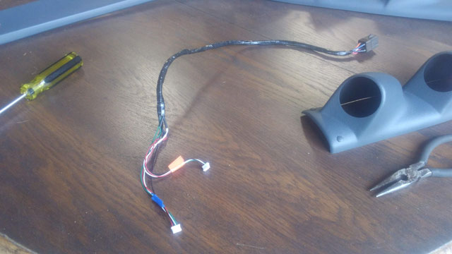 Here's the new Bosch wideband O2 sensor: 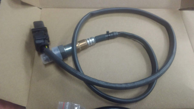 Here's the wideband controller: 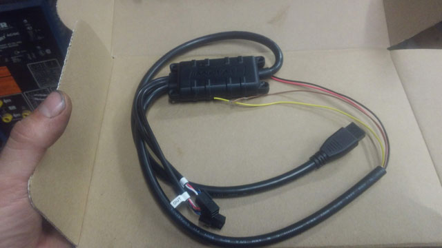 Just a couple wires to connect to make it work, plus the large plug goes to the O2 sensor, the other 2 plugs are optional. One of the small plugs is an input for connecting a laptop for tuning the controller, and the other one is an output if youre using other software/hardware from Innovate. Here's the included harness that connects the sensor to the controller. its available in several lengths; i got the 8' one because i dont know how im going to route the wire yet. 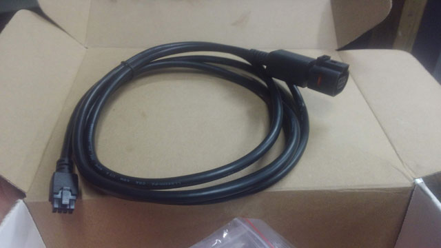 And it also included this adapter harness for connecting a laptop for datalogging or tuning the controller: 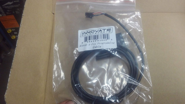 Its unlikely ill need this, but it would be useful for those who like to do more specialized tuning for racing, or want to use the controller to emulate a narrowband sensor. Ive already started wiring the controller up in the truck, but i havent routed the cable for the sensor yet. Its difficult to say exactly where i want it to go, w/o an engine or transmission in the truck to check for clearances. Hopefully the engine will come back soon, and i can get this thing back together and running! I have a torque converter on order from Broader Performance, hopefully it comes soon. I also decided its worth it to just order a tuner, so friday i ordered the PimpX ECU from Stinger Performance. So the next big part of the wiring job is the electric fan. I opted for a can controller from DC Control, specifically his model FK-75 controller. Its a PWM controller, rated for 75a continuous duty, and fully adjustable. For those that dont know what PWM is, its pulse width modulation. The short version is, it doesn't just turn the fan on, it pulses the power on & off, to control how fast the fan spins. This means you can run the fan at any speed you want, and it also means theres no big load on the electrical system when the fan starts. Most OEMs are now going this way for their electric fans, and its all over the industrial world as well since its so effective for motor control. Anyway.... So im running the windstar fan, which i installed on the radiator some time ago: 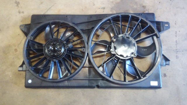 Its 2 single speed fans that Ford ran in parallel. Its not a high/low thing. 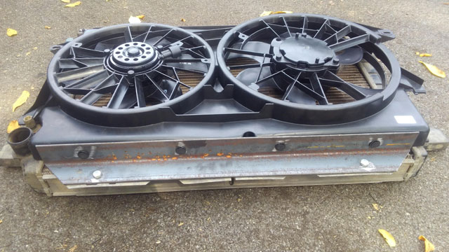 Fan controller: 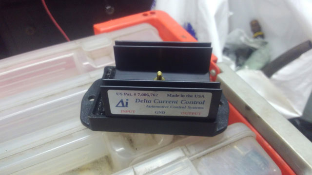 Came with everything required to wire it up, so lets get to it! 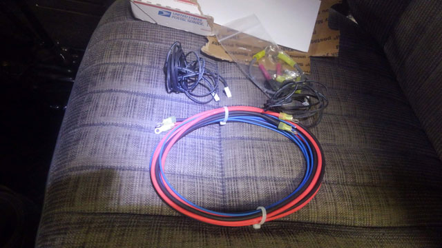 Ok, first off, i want the fan to turn on when i turn the key on. I dont want to have to turn a switch on on the dash, because that also means i can forget, and overheat the engine. Youd think youd remember, but my old fan was wired that way, and i definitely forgot once or twice! This meant i needed a relay capable of handling 60+ amps continuous duty. Well, i found one, and its more affordable than you think Obtain Surplus: 75a relay 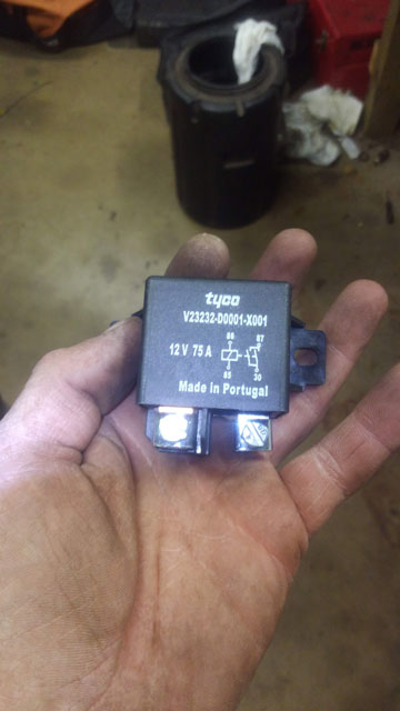 Conveniently, it fit right between my winch disconnect and the contactor. Perfectly. I didnt have to drill any holes, its the perfect spacing that its held in place by the screws from both of them: 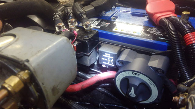 fan controller mounted: 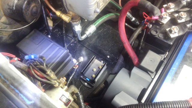 Fans wired. You can see the temp probe wiring poking out of the loom: 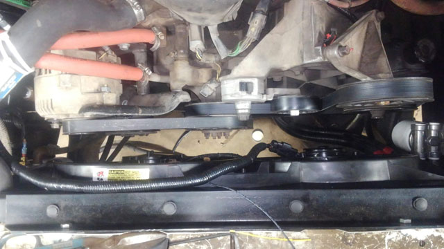 Temp probe. Its a delta temp probe that installs right in the radiator fins, and it is remarkably quick to respond to temperature change: 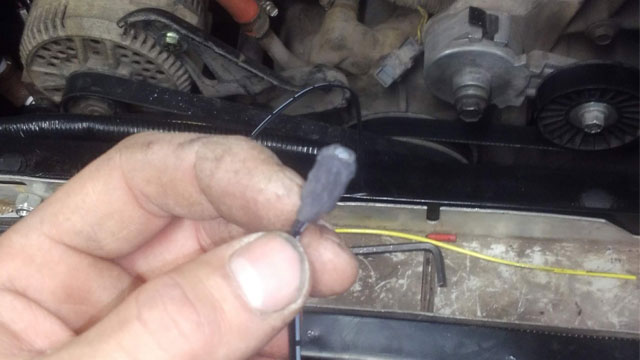 This was an interesting picture to take. I had to drill a small hole in the fan shroud for it to pass thru, and then wedge it into the fins. Then hold the fan away with one hand and try to snap a pic with the other! 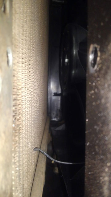 Everything all done being wired & loomed: 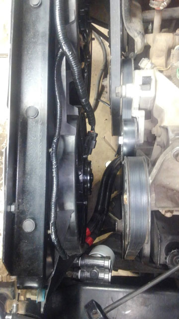 So theres an input for A/C. When the A/C is on, it automatically turns the fans on at 50%. So i tied into the output for the pressure switch, this way it only spins up if the A/C is actually working. Which currently it isnt! 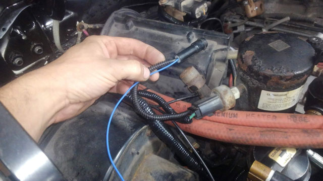 ...and there it is, the whole thing done! 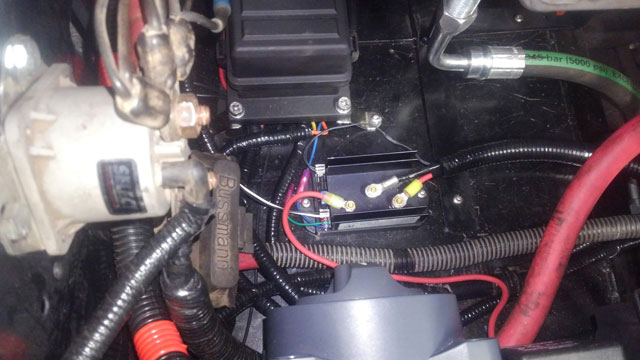 So there was nothing left to do but test the system. And it works! So, if you were paying attention, you noticed an LED next to the switch for the winch control. Well, its for the electric fan: 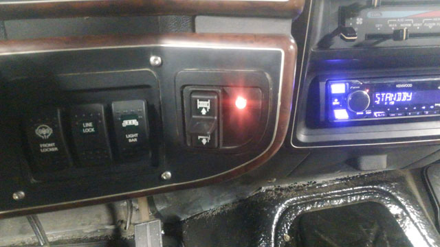 This is a feedback sensor for the fan. When the controller first turns the fan on, it will blink red. Then, it will start off green. As the fan ramps up in speed, it will turn yellow and then eventually red once its 100%, so you always know how fast the fan is spinning. So, i ran the truck for almost an hour the other day to test it, and its amazing how well it works. First off, the PWM is amazing; even at idle the volt gauge doesnt even flinch when the fan turns on. The controller ramps the fan up to speed and then turns it back off since at idle, it cools it off very fast. Even with the engine held at 1100 RPM, the fan doesnt run full speed, which is quite promising. The controller is adjustable +/- 35º, so i can fine tune it if i need it to turn on sooner or later, but my preliminary testing seems to show that its gonna work just fine. So, this concludes the wiring portion of this project! Im taking the next week to get some projects done around the yard (and cleaning the garage). Then, the truck goes up on jack stands, and we will begin rebuilding the axles and suspension. We're getting ever closer to driving this thing! So this took a while, but the end result was well worth it. All the aux wiring is done!! So, i bought a relay box off amazon: 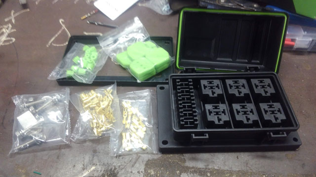 Switches are from OTRATTW. Locker, line lock, light bar & winch control switches installed: 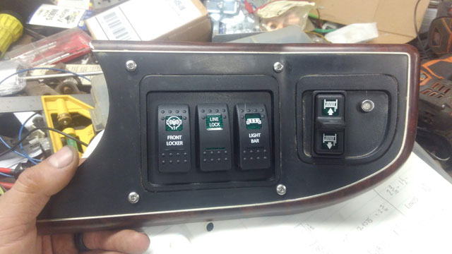 i bought 18ga 12 conductor cable from Show Me Cables to wire the switches: 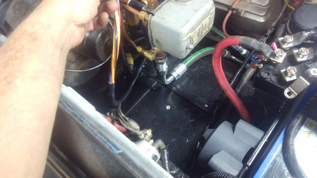 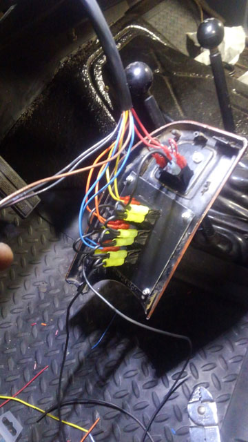 Wiring up the fuse/relay box: 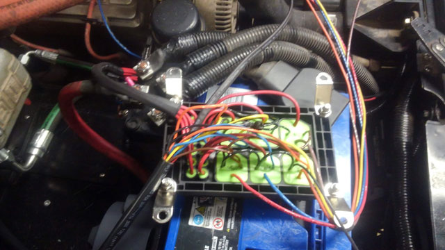 I have one standalone circuit for each accessory, plus one spare already run from the box to the dash, so if i ever want to add another switch, all the wiring is already done. Everything is color coded; the switch wiring is color matched to the individual +12 for each accessory so i cant mix up any wires. There is also a key-hot power source turning on 2 of the relays; one is for the OBA system, and the second is for the elec fan, so i dont have to worry about remembering to turn either on. 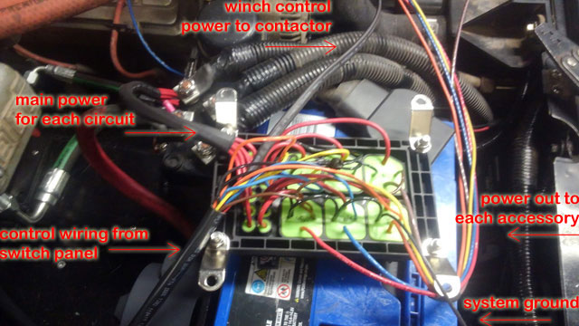 ...and installed! 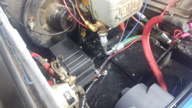 At this point, every accessory has been wired and tested for function. |